How to Configure an ifm Pressure Sensor
Integrating ifm digital pressure sensors into your machinery can be a game-changer in preventing the kind of damage or operational downtime that typically results from the wear and tear of mechanical components. Digital pressure sensors have a significantly longer lifespan when compared to traditional mechanical sensors, which often succumb to functional failures due to repeated use.
All World strategically incorporates ifm pressure sensors within its machine accessories such as CorePULL® and ClampMAX®. These sensors are expertly connected to valve stacks, offering a high degree of customization and compatibility with the Internet of Things (IoT), thus paving the way for advanced data gathering and analytics. Leveraging such technology sets the stage for continuous operational improvements.
Precise configuration of your pressure and level sensors is essential for machine accuracy and optimizing the use of your machine accessories. Here is how to configure an ifm digital pressure switch. This article utilizes the PN7070 model.
Most models are consistent in the way they are set and the parameters that are available to you to be changed. Here are just some of the many customizable settings.
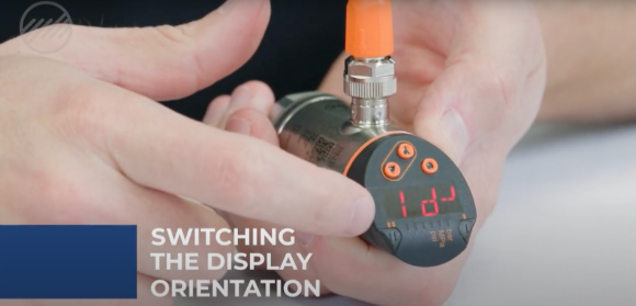
Switching the Display Orientation
Menus can be accessed by the circle button. You can scroll using the up and down arrows.
The automatic reading is rP1 which may appear upside down. To change it, scroll down to EF and select it by pressing the circle button. Then, scroll all the way down to diS which is the abbreviation for display and select it.

The default setting is D2. If you hold your down arrow, it will start to change. If you get to rd1 and select it, the display will flip and face your direction. The up and down arrows will also change orientation and will match the display.

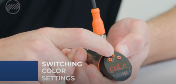
If you scroll through the menus, you will find the color selection and the display will be automatically set to red.
There is also a green color option as well as the option to have it change color when the switch is met. Hold down the down arrow while it flashes to scroll through different color options. Select the desired color by hitting the dot button.
Switching Transistor Polarity (PNP and NPN)
In our Extended Functions (EF) category, you can choose whether the switch is PNP (switch by high signal) or NPN (switch by low signal). When changing the setting, hold the down arrow. It will flash until it changes.
Switching Unit of Measurement (Pressure)
Your pressure measurement options are bar, MPa, and psi. Hold down the arrow until you can scroll through the three options. Select the chosen pressure measurement option by hitting the circle button.
You can use your down arrow to get back out of this menu.

Alternatively, you can also wait a period of time and it will take you back to the main display.
Changing the Pressure Set Points
There are two available pressure set points, SP1 and SP2.
By hitting the menu key, it will display where your current set point is. By holding the down arrow, it will flash and allow you to change it by using the up and down arrow. Press menu to save.
You can scroll down and see SP2, for a change of status at a certain pressure. Hit the circle key to see where it is set and hold the down arrow to see the status change. Then hit the circle button.
You can down arrow through the scrolling menu to get back to the main display. It will display your actual pressure. Typically, on set points, you want those to be set just below system pressure or the pressure you desire at your device.
If you were looking at a 2,000 psi cylinder, for example, you probably want your switch set roughly at 1,900 or just below that, so you are not right on the edge of what the pressure switch will see for limit.


